Spatial Processing #
Buffer #
Calculate a

bufferwith a defined distance.Dissolve: if 2 or more buffer areas overlap, they can be combined.
Attention
The unit of distance depends on the projection of the layer. For buffering you usually need a metric coordinate system such as UTM (Universal Transverse Mercator).
Example: Which regions fall within a 100-kilometer radius of major cities?
Tip
If you’re dealing with really large “megabuffers” or if you can only choose buffer distances in degrees instead of meters, it might mean there’s no metric coordinate system, or it was incorrectly reprojected. The unit of the buffer depends on the coordinate reference systems of the layer.
Clip #
With the

Cliptool you can extract and retain the spatial extent of one vector layer based on the boundaries of another layer.Input Layer: refers to the specific layer to be clipped, for instance, a road network.Overlay Layer: e.g. a polygon layer of the region (e.g. borders of Heidelberg).
Example: Extract the rail network of Germany
Dissolve #
The

dissolvetool aggregates geometries with the same attribute values.When 2 or more buffer areas overlap, they can be combined using dissolve.
Example: Extract the rail network of Germany
Attention
In QGIS, only the attributes selected for the dissolve operation will receive the accurate attribute, while the remaining attributes remain unaggregated; hence, in this example, the name is not accurately represented (e.g. the name for Western Europe might be mistakenly assigned as “Netherlands”).
Intersection #
The ![]()
intersection tool extracts the part of the layers which overlap.
In the top bar, navigate to
Vector→Geoprocessing Tool→IntersectionORToolbox→ Search forIntersection.Input layer: select layer oneOverlay layer: select layer twoIntersection: Specify where you want to save the results and give it a good name
Note
Order of input layer and overlay layer does not matter here
Possibility to keep only certain fields of the output layer
⚠️ Attention: Attribute values that refer to output areas (e.g. population) are no longer meaningful after the intersect
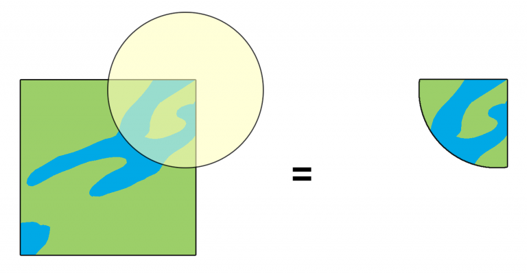
Fig. 15 Intersection operation between a two-features input layer and a single feature overlay layer (left) - resulting features are moved for clarity (right). Source: GISGeography.com#
Example: Intersect countries with timezones
Centroids #
With the 
Centroids-tool, you can create a new layer with points at the centre of each polygon.
In the top bar, navigate to
Vector→Geometry Tools→Centroids. Alternatively, search forCentroidsin the [Processing Toolbox]. Open the tool by Double-clicking on it.Input layer: select the polygon layerClick
Run.The new layer will be added to your project.